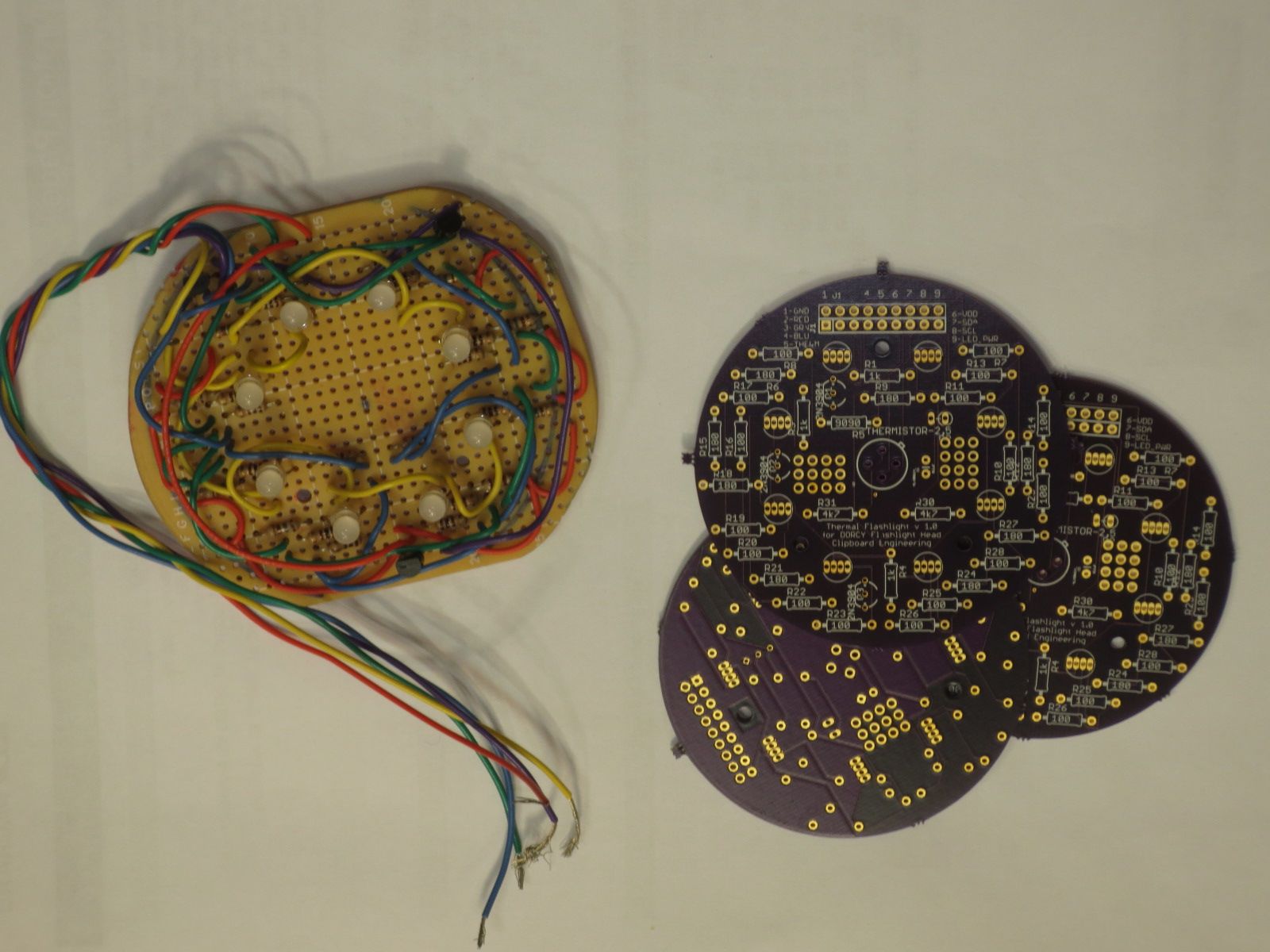
The new thermal flashlight header boards are in, and they look neat!
Alas, there was a slight glitch in my reading of an earlier circuit diagram, but that doesn’t sink us! It’s always good to give a bit of a small prototyping area on a new PCB board, so that if you need to add components (filter capacitors, indicator LEDs, etc.), it is easy to do. I’ve always included them, and they make small glitches easy to handle. It is also good to put as much documentation you can on the board, and make sure that a version number is on the board itself, so there isn’t any confusion down the road.
The header boards, along with the prototypes, are shown below.
The circuit diagram (PDF) for the updated thermal flashlight is here.
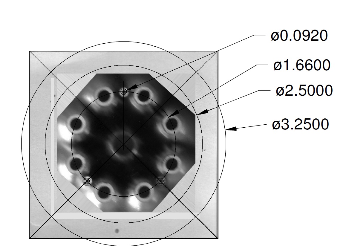
One great trick in building up this board, was to use a flatbed scanner to scan the flashlight head (with a known object in the frame) so that the mounting holes could be easily measured (then importing the picture into a drafting program, in order to get the proper dimensions). The Dorcy flashlight is a simple and cheap consumer product, and not the kind of device you find in the industrial controls world, where everything (including the physical dimensions of the hardware) is documented nicely. Worked liked a charm, I must say.
Here’s the first scan of the Dorcy flashlight head and a reference item (a Post-It note):
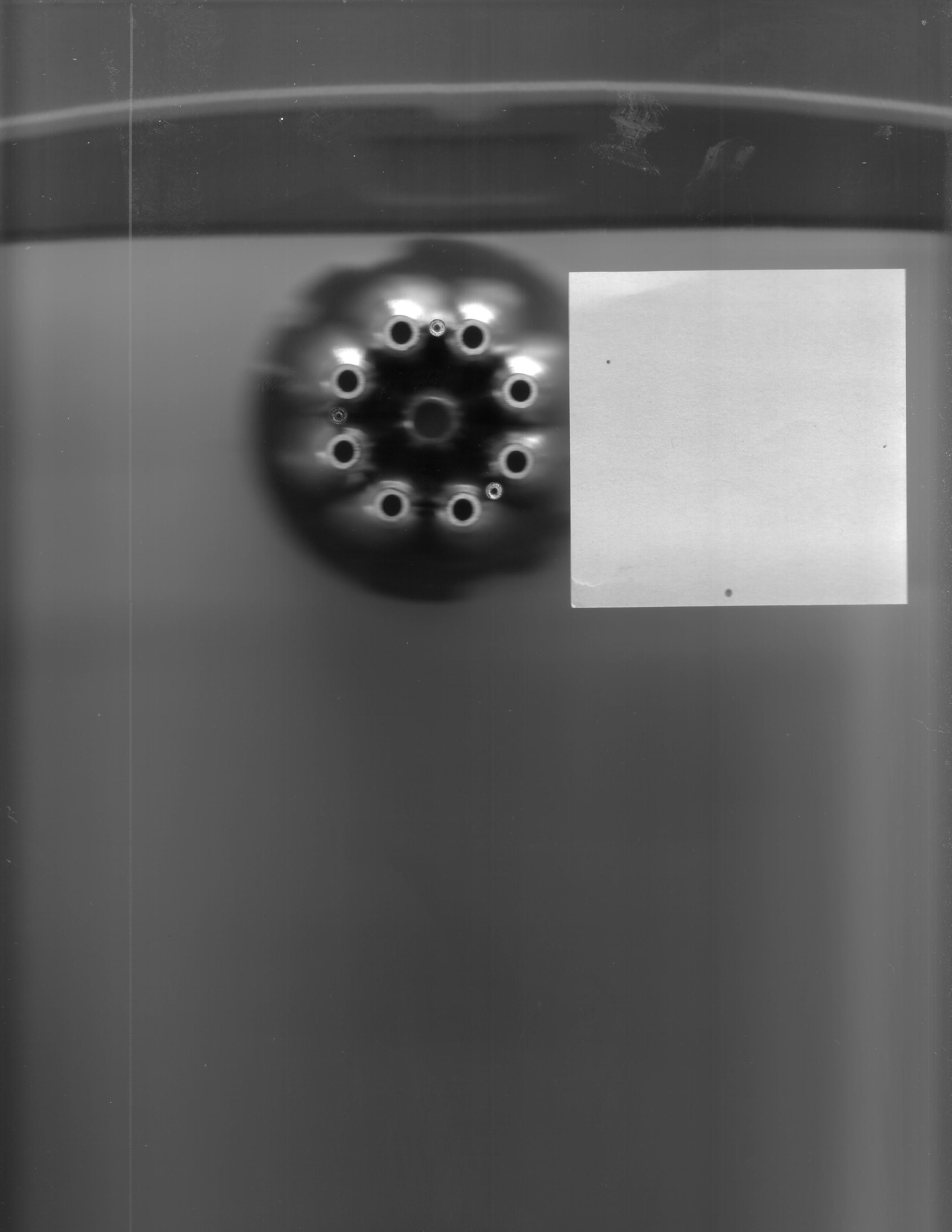
After a few tricks with image software (cutting, pasting, rotating) and a drafting program, we can get to measuring things. Here, the head of the flashlight is shown against a Post-It note. Since the dimensions of the Post-It note are known pretty well, designing the interface with the PCB was a piece of cake.